70 cm 250 Watt PA

Home Up 70 cm 250 Watt PA mast at remote mast at qth 47 GHz new system vsat alford loop Perseus GPSDO repair measuring equipment Cloudwatcher Radio Direction Finder fountain

Stop Russian war against Ukraine


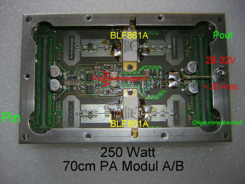
PA Leistungsmodul für 70cm Band,  28-32 Volt / ca. 20 Amp

On Ebay in Germany I found this module, bought it for 64 Euro


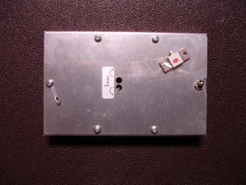
Module as it arrived


After mounting this on a suitable heat sink and adding some connectors to it I started testing with 28 Volts


Power output and gain were disappointing
I could get about 150 Watt with 20 Watt drive with full compression

After increasing the supply voltage to 32 Volt power output increased to 175 Watt

When looking at the specifications of the BLF861A then it was clear that the amplifier was not working as it could
download the Specifications from the BLF861A

I started measuring the gain of the amplifier at different frequencies
Using a signal generator at 10 milliWatt I measured output at different frequencies
 

Frequency (MHz) output power (mWatt) Gain (dB)
432 150 11,7
448 175 12,4
548 225 13,5
580 170 12,3
648 120 10,8
800 60 7,7

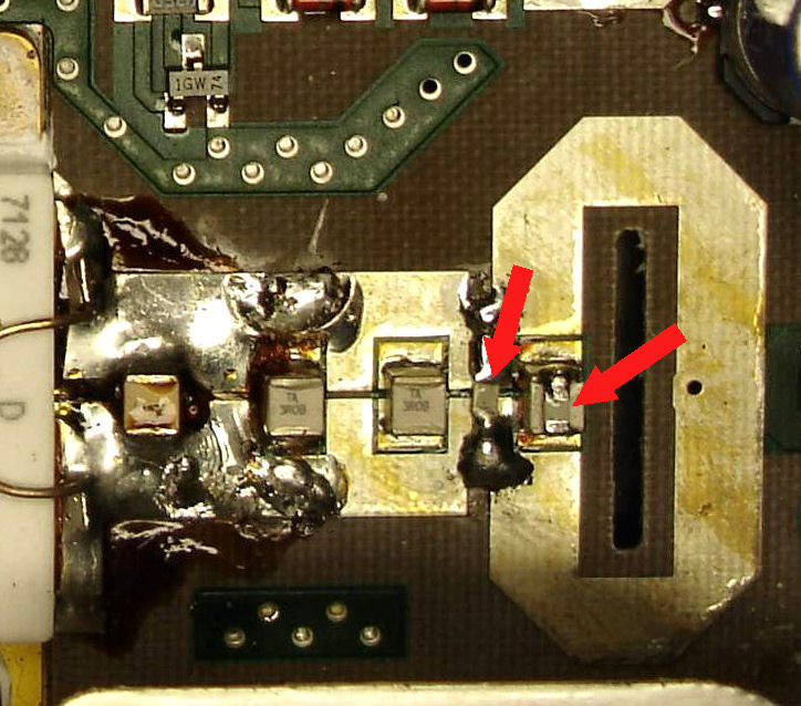
I decided to try and see if I could optimise the amplifier
After adding two tuning capacitors at the input I increased gain from 11,7 dB to 18,9 dB so quite a lot difference

Power output increased to 200 Watt max.

I tried adding a tuning capacitor on the output and power output increased to 250 Watt with 17 ampere total current, I replaced this with two small SMD capacitors of 5,6 pF on each output of the BLF861A so 4 in total
 

With 5 watt power drive the output power was 250 Watt a gain of 17 dB


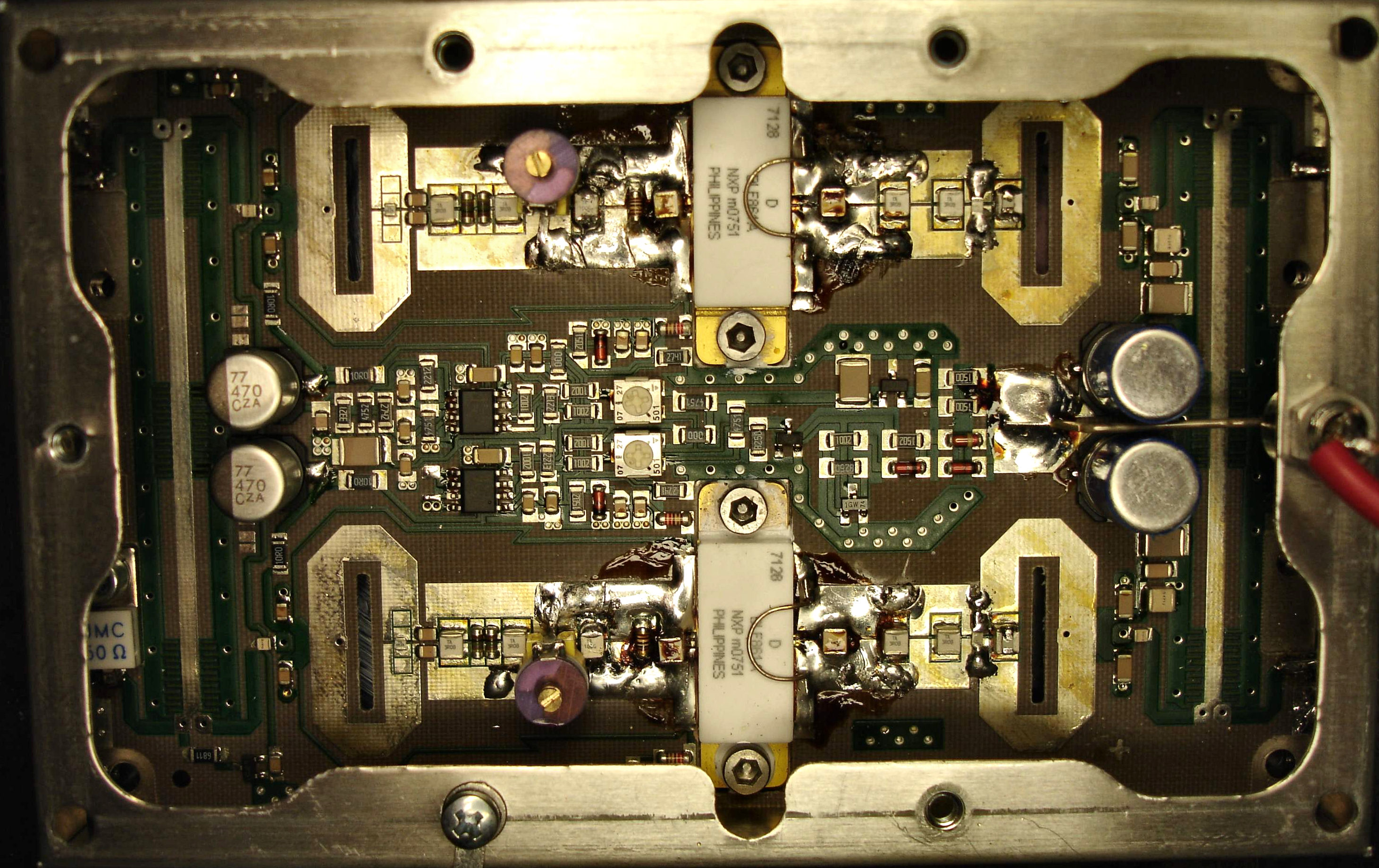
I got some questions to further explain what I did so here is a bit more explanation.
 

I added on the input of each transistor a trimmer see the picture above.
The maximum capacitance of the trimmer is 45 pF

I added on the output of each transistor two SMD capacitors, nothing special, of 5,6 pF
On the picture below is visible were I did put these,
the capacitor on the right is mounted on top of the capacitor which is already on the circuit.

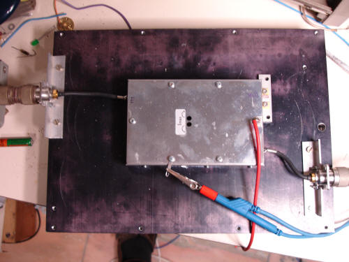
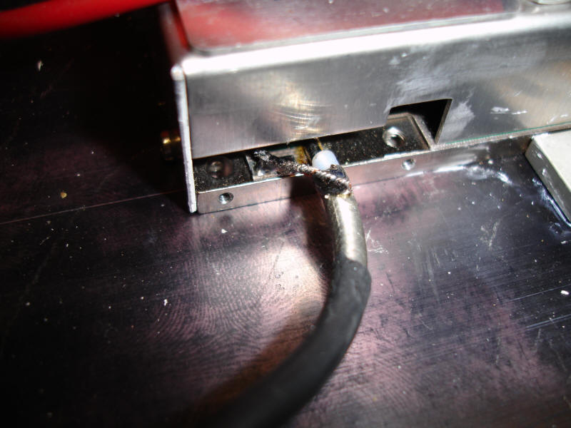
The way I mounted the coax cable:
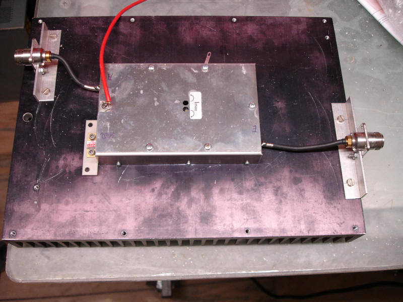
The total amplifier ready for use,
the output dummy is mounted on a small alu block to level of the connecting strip to the circuit board.


Some lessons from other Hams who made these modifications:

Do not remove the housing from the amplifier, leave the housing on as it is.

If you remove the housing and do the modification you have big risk that the amplifier starts oscillating.

After modification max drive power needed is about 5 W to get 250 Watt output.

Use a good reliable power meter to measure output.


I also have a schematic diagram available and some spe4cifications from the amplifier
These can be downloaded
Schematic diagram
Specification